
Instrumentation
Instruments located on jacketed pipelines
Process experts recommend jacketed or traced pipelines based on fluid properties and site weather conditions.
Here we briefly address the engineering guidelines for instruments located on jacketed pipelines. To understand the instrument connections on jacketed pipelines, one needs to understand jacketed piping systems: their P&ID representation and the required connections.
General introduction to jacketed piping systems
Jacketed pipelines are generally used in process piping systems where solidification of the process medium may occur, or where jacketing is used as an anti-frost measure as recommended by process experts.
Jacketed pipelines help to convey complex process fluids (i.e. very viscous or likely to solidify) in an inner pipe, heated by steam, hot water, hot oil or another heating medium between the jacket and the core pipe.
Vacuum jacketing is also used as an insulator for cryogenic fluids.
Generally, the outer jacket pipeline is one size higher than the inner core pipeline, up to a certain line size. However, the project-specific piping specifications for jacketed pipelines shall be referred to for the details.
There are two types of jacketed pipelines:
Continuous / fully jacketed
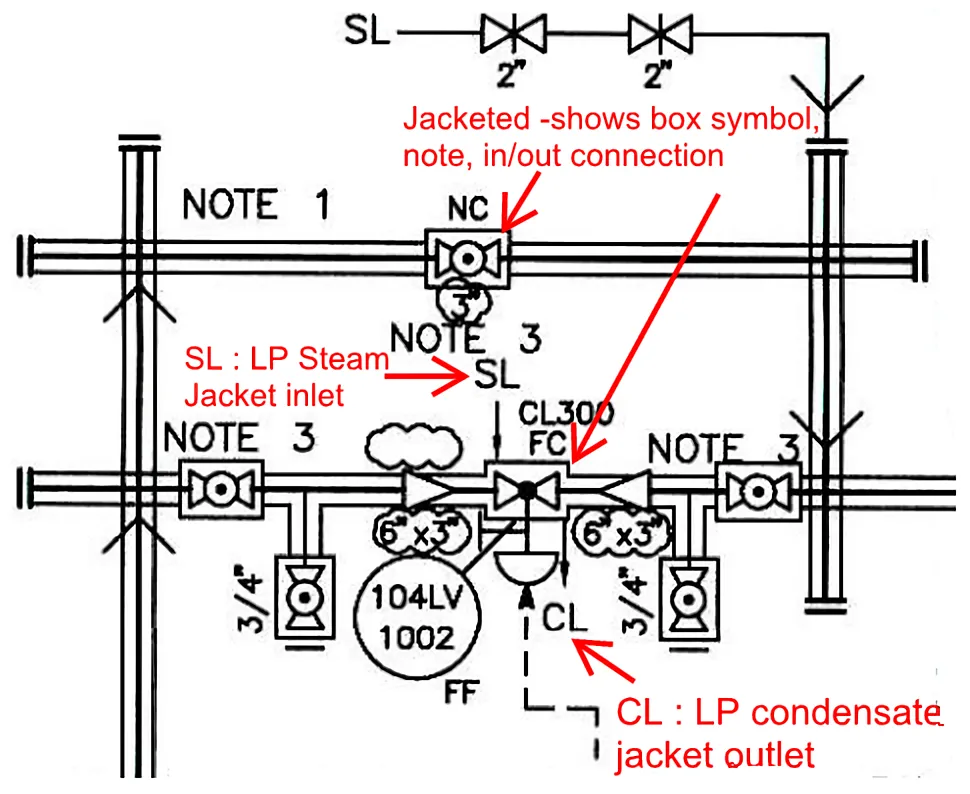
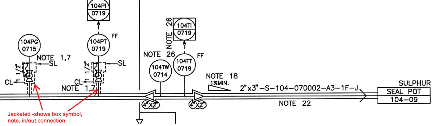
All straight lengths, flanges, fittings, valves and branch connections are fully jacketed. The jacket is generally shown by a box around the item in the P&ID. There may be a note in the P&ID referring to the jacketed item.

Typical P&ID representation of fully jacketed pipelines:
For clarity, one needs to understand fully jacketed and partially jacketed type pipelines with respect to the pipe material specifications.
Example 1: Fully jacketed line showing jacketed valves
Example 2: Fully jacketed line showing jacketed isolation valves
Discontinuous / partially jacketed
In the case of partially jacketed pipelines, only the straight lengths of pipe are jacketed. Flanges, tees, elbows, branch connections and welds are not jacketed.

Or sometimes there is less possibility of the fluid solidifying in the pipeline while it is flowing, but it may solidify in the nozzle. In such cases, the pipelines are not jacketed and the nozzles are jacketed. Or jacketing is only considered for the straight lengths and for the nozzles, based on process recommendations.
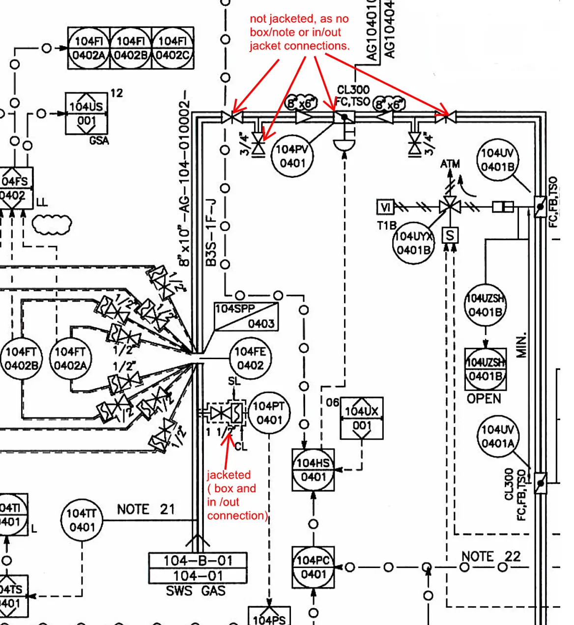
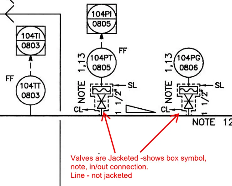
Various types of partially jacketed lines are shown in the P&IDs as below:
Example 3: Pipeline is jacketed but inline valves are not jacketed
Example 4: Pipeline is not jacketed but isolation valves are jacketed
Example 5: Pipeline is not jacketed (it is traced) but isolation valves are jacketed
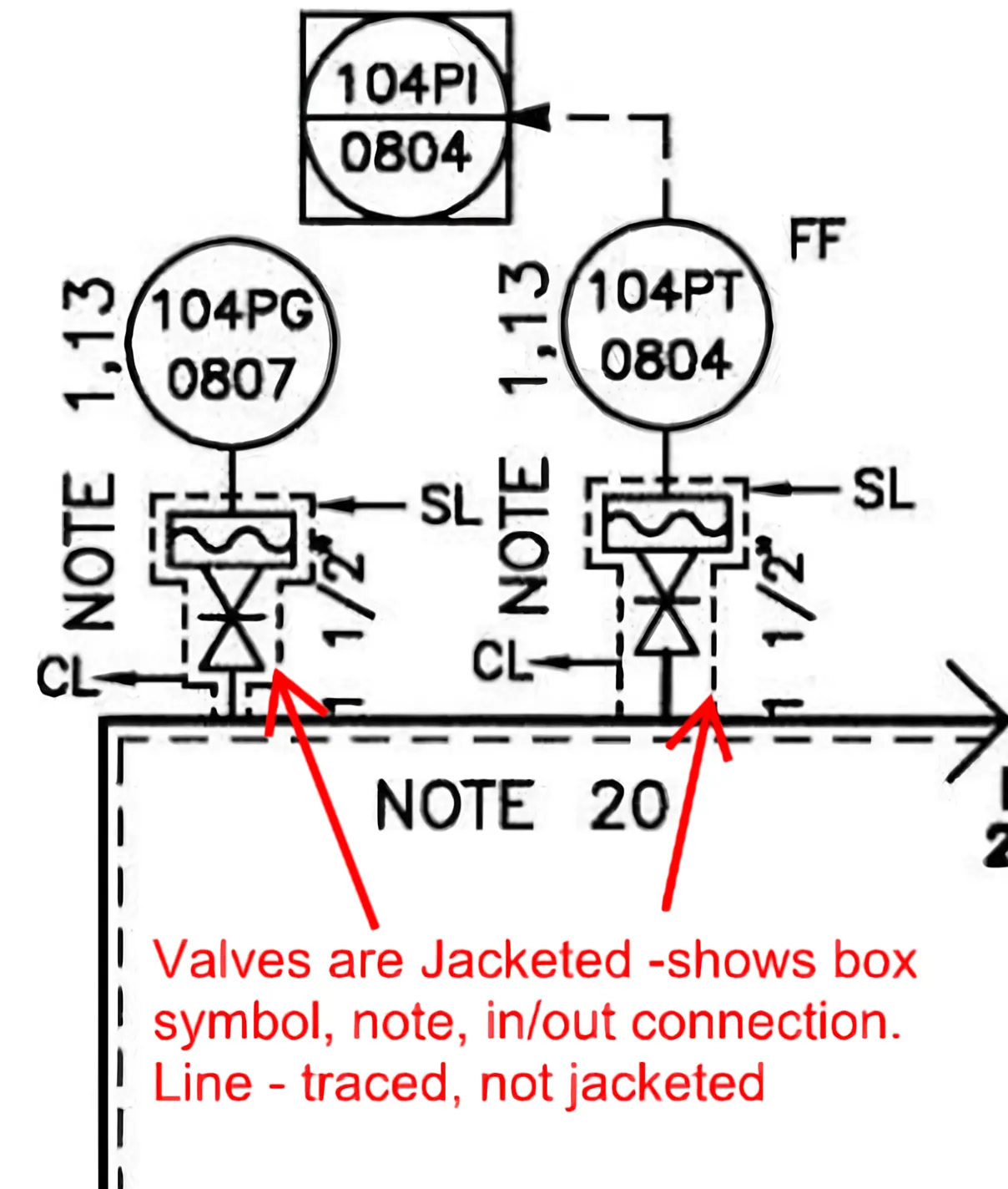
Jacketing connections in both types
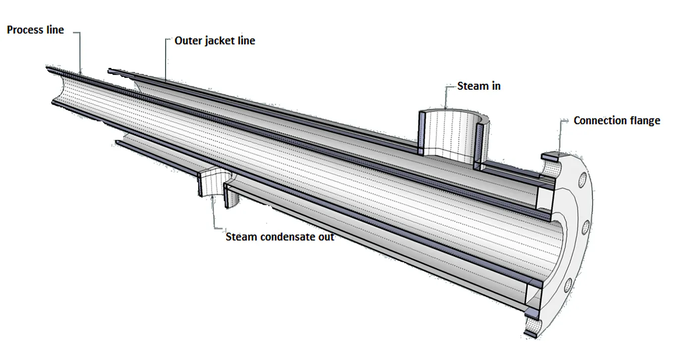
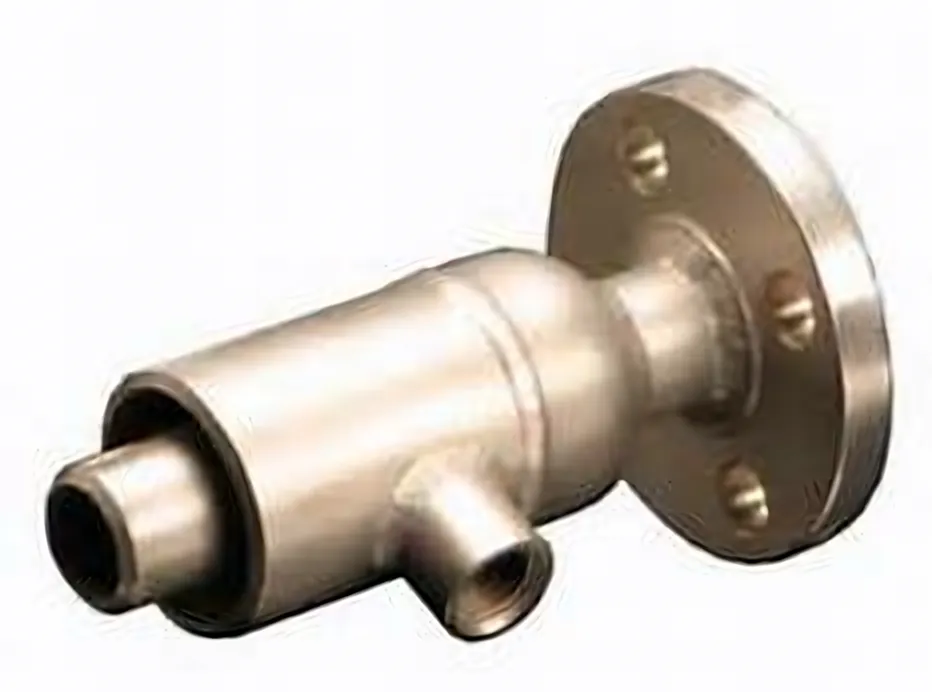
In the case of a fully jacketed pipeline, the outer jacket pipe is welded to the back of the (modified) end flange of each jacket section. The inner pipe is welded into the modified flange, as shown below:
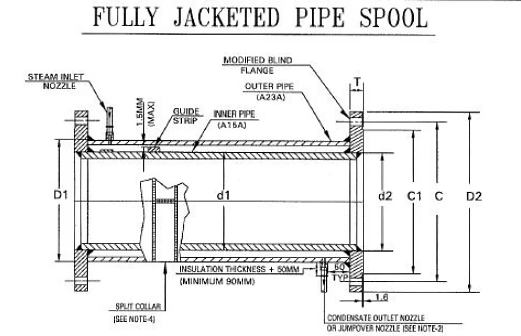
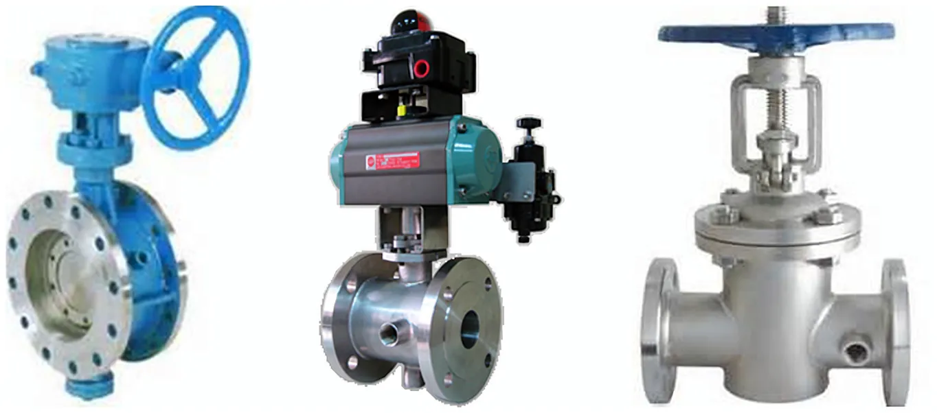
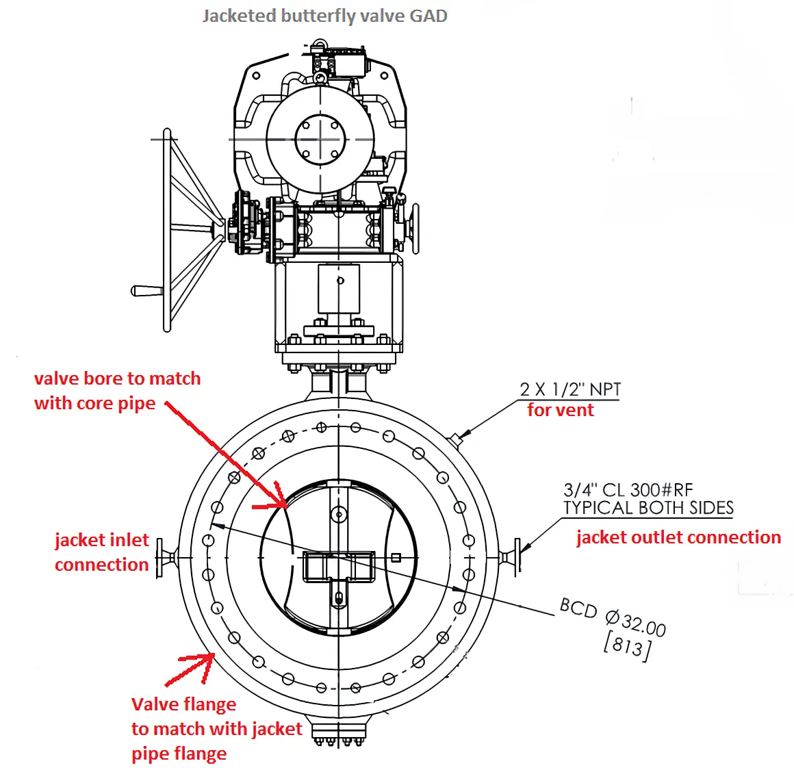
In this case, valves are bought as jacketed valves, with flanged inlet and outlet connections for the jacketing medium. Jacketed valves have a standard bore (to match the core pipe) and oversized flanges (to match the jacket pipe flanges).
Typical fully jacketed pipe:
Typical jacketed valves:
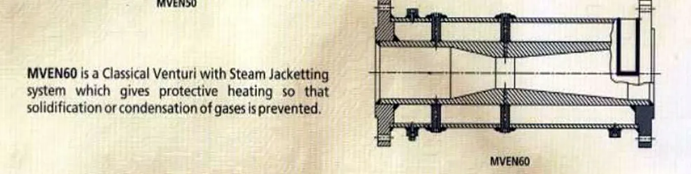
Typical jacketed flowmeters:
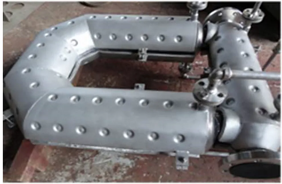
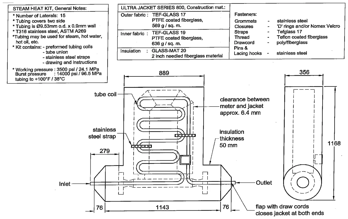
Mass flow meter:
For discontinuous/partial jacketing, the end of the jacketing is welded to the inner pipe.
Typical partially jacketed pipe:
Engineering guidelines for instruments located on jacketed pipelines (full or partial)
Inline instruments
For inline instruments, the jacketing requirement shall be considered as per the guidelines below:
- The jacketing requirement shall be considered as per the P&ID representation (i.e. the jacket symbol), notes etc. Queries, if any, shall be discussed with piping and process at the beginning of the project.
- For clarity, understand the jacketing requirement with respect to the pipe material specifications.
- Jacketed inline instruments shall have a standard bore (to match the core pipe) and oversized flanges (to match the jacket pipe flanges), with flanged inlet and outlet connections for the jacketing medium as per the project specifications.
- For jacketed instruments, details such as the jacketing medium process data, material, jacketing inlet and outlet connections and the related project specifications shall be communicated to the instrument vendor.
- A proven track record for the supply of jacketed instruments shall be obtained from the instrument vendor, in order to avoid post-order issues.
Offline instruments
For offline instruments, the jacketing requirement shall be taken care of as below:
- The jacketing requirement shall be considered as per the P&ID representation, i.e. if the root/isolation valve (i.e. the nozzle mating connection) is jacketed, then the instrument-side mating connection shall be as per the jacketing connection guidelines mentioned in the piping specifications, i.e. generally one size higher than the inner core pipeline, up to a certain line size.
- Refer to the project specifications. If the main line and nozzle are jacketed for offline instruments, then the related impulse piping/tubing may require tracing/jacketing, a special size etc. The requirement shall be taken care of accordingly while engineering.